
If you have questions on MEAN WELL’s products, please read the FAQ first. If the listed answers still cannot solve your problems, please contract our local distributors , they should reply to you as soon as received your request.
As a dedicated manufacturer of standard power supplies, MEAN WELL provides a wide variety of power supplies to meet different demands from the markets. However, selecting the right products relies heavily on the correct electrical characteristics and specification, we listed the frequently asked questions for your reference.
Functionality Aspect
What is power good and power fail signals and how can use it?
Some power supplies provide a "Power Good" signal when they are turned on, and send out a " Power Fail" signal when they are turned off. This is usually used for monitoring and controlling purpose.
Power Good: after the output of a power supply reaches 90% rated voltage, an TTL signal (about 5V) will be sent out within the next 10-500ms.
Power Fail: before the output of a power supply is less than 90% rated voltage, the power-good signal will be turned off at least 1ms in advance.

What is minimum load requirement and how can I read it from the spec?
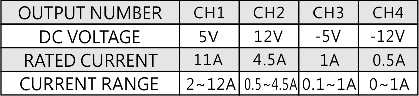
There are some minimum-load requirements on MEAN WELL's multi-output power supplies. Please read the specification first before connecting to the load. In order to allow the power supply to work properly, a minimum load for each output is required, or else, the output voltage level will be unstable or outer tolerance range. Please refer to “Current range” in the specification as shown in the table below: Channel 1 requires a 2A minimum-load; channel 2 requires 0.5A; Channel 3 requires 0.1A ; Channel 4 does not need any minimum-load.
What is "Inrush Current"? What will we notice?
At input side, there will be (1/2 ~1 cycle, ex. 1/120 ~ 1/60 seconds for 60 Hz AC source) large pulse current (20~100A based on the design of S.P.S.) at the moment of power on and then back to normal rating. This "Inrush Current" will appear every time you turn on the power. Although it will not damage the power supply, we suggest not turning the power supply ON/OFF very quickly within a short time. Besides, if there are several power supplies turning on at the same time, the dispatching system of AC source may shut off and go into protection mode because of the huge inrush current. It is suggested that these power supplies start up one by one or use the remote control function of S.P.S. to turn them on/off.
What is PFC?
Power Factor Correction or PFC is to improve the ratio of apparent power to real power. The power factor is around 0.4~0.6 in non-PFC models. In models with PFC circuit, the power factor can reach above 0.95. The calculation formulas are as follows: Apparent Power=Input Voltage x Input Current (VA), Real Power= Input Voltage x Input Current x Power Factor (W).
From the point of view of environment friendly, the power plant needs to generate a power which is higher than apparent power in order to steadily provide electricity. The real usage of electricity is defined by real power. Assuming the power factor is 0.5, the power plant needs to produce more than 2WVA to satisfy 1W real power usage. On the contrary, if the power factor is 0.95, the power plant only needs to generate more than 1.06VA to provide 1W real power, It will be more effective in energy saving with PFC function.
Active PFC topologies can be divided into single-stage active PFC and two-stage active PFC, the difference is show as in the table below.
| PFC topology | Advantage | Disadvantage | Limitation |
| Single-stage active PFC |
Low cost Simple schematic High efficiency in small watt application |
Huge Ripple complex feedback control |
1.Zero “hold up time”. The output is affected by the AC input directly. 2.Huge ripple current results in lower LED life cycle.(drive the LED directly) 3.Low dynamic responds, easily affected by load. |
| Two-stage active PFC |
High efficiency Higher PF Easy feedback control High adoptive against load condition |
Higher cost Complex schematic |
Suitable for all kinds use |
What is the difference between -V and COM which are marked on the output side?
COM (COMMON) means common ground. Please see below:
Single output: Positive pole (+V), Negative pole (-V)
Multiple output (Common ground): Positive pole (+V1, +V2,.), Negative pole (COM)
In MEAN WELL's catalog, we see AC and DC at input, what is it all about?
Due to different circuit designs, MEAN WELL power supply's input consists of three types as below:
(VAC≒VDC)
a.85~264VAC;120~370VDC
b.176~264VAC;250~370VDC
c.85~132VAC/176~264VAC by Switch; 250~370VDC
-
- In a and b inputs models, power supply can work properly no matter under AC or DC input. Some models need correct connection of input poles, positive pole connects to AC/L; negative pole connects to AC/N. Others may require opposite connection, positive pole to AC/N; negative pole to AC/L. If customers make a wrong connection, the power supply will not be broken. You can just reverse the input poles and power supply will still work.
- In c input models, please make sure that you switch the 115/230V input correctly. If the switch is on the 115V side and the real input is 230V, the power supply will be damaged.
What is MTBF? Is it distinct from Life Cycle? What is DMTBF?
MTBF (Mean Time Between Failure) and Life Cycle are both indicators of reliability. MTBF can be calculated by two different methodologies, which are “part count” and “stress analysis”. The regulations, MIL-HDBK-217F Notice 2 and TELCORDIA SR/TR-332(Bellcore) are commonly used to calculate MTBF. MIL-HDBK-217F is a United States military standard, and TELCORDIA SR/TR-332(Bellcore) is a commercial regulation. MEAN WELL utilize MIL-HDBK-217F(Stress Analysis) as the core of MTBF. The exact meaning of MTBF is, after continuously using the power supply for a certain amount of time, the average time that the probability of proper operation is down to 36.8%(e-1=0.368). Currently MEAN WELL is adopting MIL-HDBK-217F, forecasting the expected reliability through Stress Analysis (excluding fans); this MTBF means the probability of the product can continue the normal work after working continuously up to the calculated MTBF time is 36.8% (e-1=0.368). If the power supply is continuously used at double the MTBF time, the probability of proper operation becomes 13.5%(e-2=0.135). Life Cycle is found by using the temperature rise of electrolytic capacitors under maximum operating temperature to estimate the approximate life of the power supply. For example, RSP-750-12 MTBF=109.1K hours(25°C); electrolytic capacitor C110 Life Cycle=213K hours (Ta=50℃)
DMTBF(Demonstration Mean Time Between Failure) is a way of evaluate MTBF。Please refer to the following equation for MTBF calculation.


MTBF:Life time determine by specification.
X2:Can be found in chi-square distribution
N:Number of sampling
AF:Acceleration factor, which can be derived from acceleration factor equation.
Ae=0.6
K(Boltzmann Constant)=(eV/k)
T1:Rated temperature of specification. Note: Kelvin will be the unit use for calculation
T2:The temperature that is used in the meaning of acceleration, and the chosen temperature could not result in physical change in materials. Note: Kelvin will be the unit use for calculation.
What is Ripple & Noise? How to measure it?
It is the small unwanted residual periodic variation of the direct current (DC) output of a power supply which has been derived from an alternating current (AC) source. The wave form is shown as figure below.

There are two AC contents, also known as Ripple and Noise (R&N), on the DC output. The first one, coming from sine wave rectification, is at a low frequency which is 2 times of the input frequency; the second one is at high frequency which is from the switching frequency. For measuring high frequency noise, configurations of an oscilloscope with a bandwidth of 20MHz, a scope probe with shortest ground wire possible, and add 0.1uF and 47uF capacitors in parallel with test point for filtering out noise interference are requires to be made.

What is Withstand Voltage?How to measure it?
Indicates Hi-Pot Test or Electric Strength Test. The input should be shorted together as well as the output before test. The test will proceed under particular loop, such as I/P-O/P, I/P-FG and O/P-FG with certain high voltage value for 1 minute. (The typical leakage current is 25mA when testing with AC)
.jpg)
- Hi-Pot Test is a way to ensure if the isolation between primary to secondary is done properly, preventing damaging to S.P.S. when facing high voltage between input and output. The test voltage should be gradually increased from 0V to preset level and remains at preset level for 60 seconds with raise time greater than 1 second. In mass production, the test period could be reduced to 1 second. If the leakage current flowing through the isolation material increases rapidly when applying test voltage, it indicates ineffectiveness of isolation (dielectricbreakdown). Corona effect/discharge or transient electrical arc is not considered as failure.
- When AC test voltage is applied, Y capacitors are the main cause of leakage current. A 4.7nF capacitor can cause leakage current of 5mA. According to regulations of UL-554, the Y capacitors should be removed for Hi-Pot test, which is not practical for mass production. The only solution is to increase the leakage current setting, typically 25mA, of test instrument. Presently, the criteria of leakage current are not defined in safety regulations.
- According to regulations of IEC60950-1, DC test voltage can be substituted when there are bridging capacitors coupled between primary and econdary circuits, so as to solve the problem of leakage current.